25 KiB
| title | media_order | published | routable | visible |
|---|---|---|---|---|
| new course : overview | objeto-fisico-imagen-virtual-haz-3-rayos-bb.jpg,objeto-fisico-imagen-virtual-pantalla-bb.jpg,objeto-imagen-posicion-tamano-bb.jpg,objeto-imagen-bb.jpg,objeto-imagen-3-rayos-bb.jpg,plano-imagen-real-convergencia-bb.jpg,plano-imagen-real-convergencia-pantalla-bb.jpg,plano-objeto-fisico-bb.jpg,vision-object-b.jpg,imagerie-rays-optics.gif,vision-object-image-2.jpg,vision-image.jpg,axe_opt.gif,plano-objeto-plan-image-bb.jpg,objeto-imagen-haz-3-rayos-bb.jpg,objeto-fisico-imagen-virtual-haz-3-rayons-pantalla-bb.jpg,plano-objeto-plano-imagen-real-pantalla-bb.jpg,sym_rev_2.gif,imagerie-rayons-lens-1.jpg,imagerie-rayons.jpg,imagerie-rays-optics.jpg | true | true | false |
What is optical imaging ?
Objective
-
Optical $\Longrightarrow$ visible range + near infrared + near UV
-
to realize optical images of physical objects to be seen with the naked eye or to be captured by an image sensor.
-
by the use of simple optical elements which can be combined in optical systems to form optical instruments.
Physical object
-
Physical object : large (compared to $\lambda_{optical}$) *volume* of matter (liquid or solid) whose *external surface can mentally be broken down in a huge number of microscopic surfaces*.
-
Physical object point = point source :
- microscopic surface part of the overall surface of the physical object.
- emits or diffuses light in all direction outside the volume. That means in equivalent ways : emits a spherical wave (wave optics), emits light rays (ray optics), emits photons (quantum optics) that diverge from the object point. -
Point source pencil of light = bundle of rays : part of the light emitted by a point source that intercept an optical system or pass through a limiting aperture.
- naked eyes = direct vision of an object : pencils from all visible point sources of the object intercept the pupil of the eye.
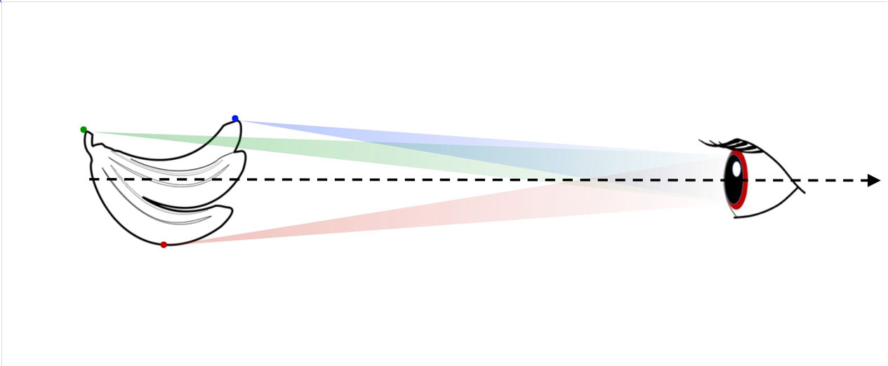
Fig. 1. Direct vision : the pencils of each visible point souces intercept the pupil of the eye.
Optical image
-
The object is seen from a specific angle of view, whose principal direction named line of sight defines (when oriented positively in direction of the eye) the optical axis of the imaging system.
-
The part of the light that diverge from any point source of the object and intercept the imager, after interaction converges in a new point in space named real image point, or diverges from a new point in space named virtual image point.
-
Image : set of all real and virtual image points.
-
form consistency between initial object and its image, but shape distortions may appear.
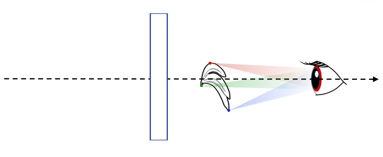
Fig. 2a. Image vision : an optical imager (rectangle) has modified the incident pencils. Only pencils from image points enter my eyes. here the image points are real.
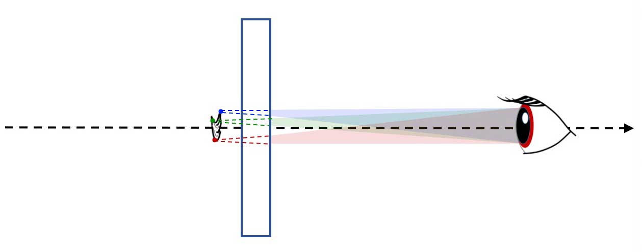
Fig. 2b. here the image points are virtual.
Optical imager and basis physical principles.
Imager :
-
Intercept part of the light emitted or diffused by the physical object.
-
modify the pencils of light from each object point, to give a new pencil that :
- converges into a new point in space $\Longrightarrow$ concentration of light energy at this point. - diverges from on other new point in space $\Longrightarrow$ no concentration of light energy at this point.
Optical imager :
- create a true three dimensional image of the extended object surface oriented towards the imager.
- use refraction and/or reflection phenomena.
- An imager can be : individual thin simple optical element or centered optical system
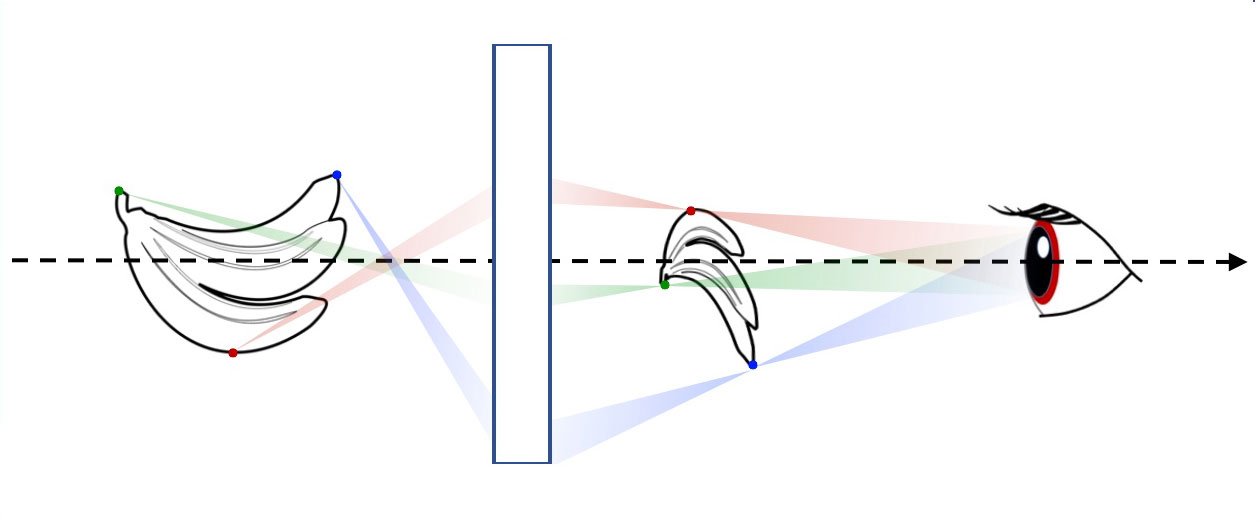
Fig. 3a. Using refraction and/or reflection phenomena, an optical imager modifies all incident pencils from each point source,to give emerging pencils that actually focus the light energy of the source points into real image points, or pencils that diverge from virtual image points. Here a real image is observed.

Fig. 3b. Here a virtual image is observed.
Thin simple optical element
- often has a symetry of revolution about an axis.
Fig. 4. Simple optical element : refracting or reflecting element, rotationaly symmetrical around an axis.
-
Thin $\Longrightarrow$ diameter $\gg$ thickness or depth.
-
Simple : surfaces of simple optical element are plane or spherical.
-
Thin optical elements studied are :
- plane or thin spherical refracting surfaces.
- plane or thin spherical mirrors.
- thin lenses.
Centered optical systems
-
Combination of thin simple optical elements centered on a common axis that becomes the optical axis of the system (when positively oriented in direction of the incident light on the system).
-
Interest : can be characterized as a whole.
Fig. 5. Centered optical system : combination of thin simple optical elements, centered on a same optical axis.
What physical framework to describe optical imaging ?
From mathematical idealization to physical reality
-
Point : mathematical concept of vanishing volume.
has a location in space, but no extension, no orientation. -
Image point physical meaning : the pencil emerging from the imager focuses on a so small volume that its extension can be neglected.
- extension of the volume can not be resolved with naked eye.
- surface illumated in the sensor plane is below the size of a pixel. -
perfectly stigmatic optical system : gives one image point for each object point (don't exist).
-
quasi stigmatic optical system : under certain conditions of use a set of optical elements is quasi-stigmatic and so becomes an imager.
-
Optical imager = quasi-stigmatic optical element or system used to give images.
Framework of the paraxial approximation in Ray optics.
-
We use the concept of light ray, coming from Ray optics
-
Ray optics = geometrical optics
-
When optical systems are considered stigmatic, their study is carried out in the framework of paraxial ray optics.
-
paraxial ray optics = paraxial approximation of Ray Optics = paraxial approximation of Geometrical Optics.
-
A light pencil that diverges from a point source, is modified by an imager and after emergence, converges to a real image point or diverges from a virtual image point.
equivalent to
- All rays emerging from a point source are deviated by the imager and cross back on a corresponding real image point, or their extensions intersect at a corresponding virtual image point.
$\Longrightarrow$ knowledge of only two different rays from a same point source through the imager is sufficient to determine image position. -
For any object point of any imager, trajectories of 3 specific rays will be specified.

Fig. 6a. Ray optics : 3 specific ray are specified (2 are sufficient) to locate the image point of any object point. In this figure the imager is a thin converging lens, and for this object position the corresponding image is real.

Fig. 6b. In this figure the imager is a thin diverging lens, and for this object position the corresponding image is virtual.
How is modeled and characterized a thin simple optical element in paraxial rays optics?
Thin simple optical element
-
Thin simple optical element = optical element whose thickness can be neglected in front of diameter $\Longrightarrow$ represented by a plane (Elt).
-
Thin simple optical elements* are **rotationally symetrical around an axis** :
$\Longrightarrow$ same optical behavior in all plane containing the axis of symetry.
$\Longrightarrow$ *object point and conjugate image point belong to a same plane that contains the axis of symetry.
$\Longrightarrow$ working in the **sectional view** corresponding to that plane is **sufficient**. -
Representation on a sectional view containing the optical axis: straight line [Elt] perpendicular to the optical axis.
-
Location with its vertex S : intersection of [Elt] with the optical axis.
Optical behavior
- - At each object point B corresponds to a unic image point B'.
- At each image point B 'corresponds a unic object point B :
$\Longrightarrow$ B and B' are conjugate points.
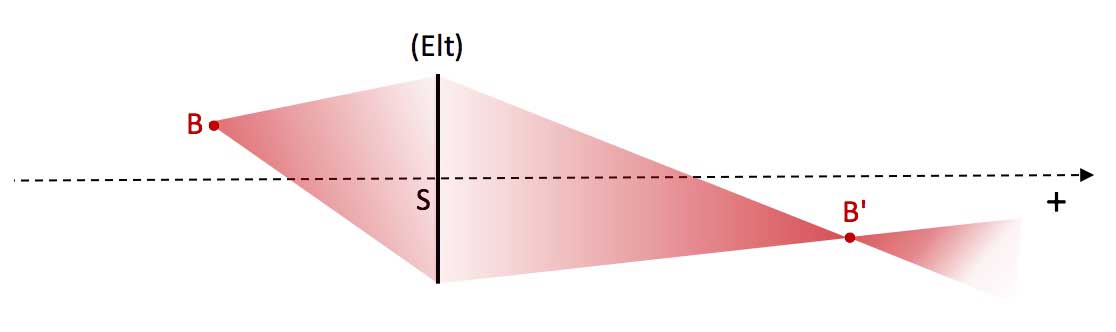
Fig. 7a. The pencil coming from point source B intercepts the thin optical element. The corresponding emerging pencil converges on the point image B', which is a real image point because the light energy is concentrated at the point B'.
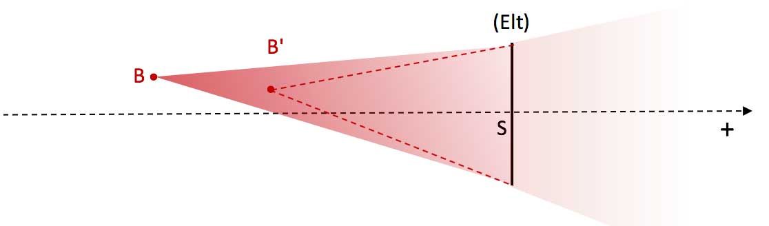 Fig. 7b. The pencil coming from point source B intercepts the thin optical element. The corresponding emerging pencil still diverges. But its extension shows that it diverges from an image point B' which is a virtual image point, because the light energy continues to disperse in space : no energy concentration in B'.
- All object point (A ; B, C, ...) of an object plane (PO) perpendicular to the optical axis have conjugated points images (A' ; B', C', ...) in a same image plane (PI) perpendicular to the optical axis :
$\Longrightarrow$ (PO) and (PI) are conjugate planes.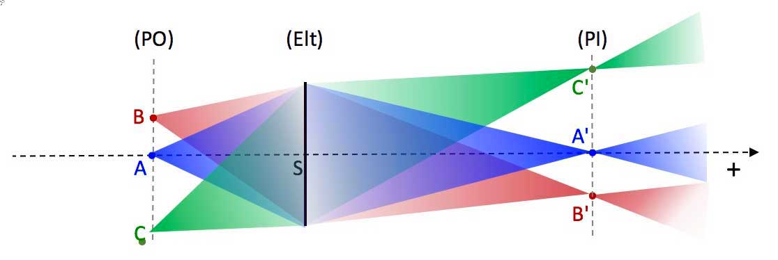
Fig. 8.
Coordinates to locate object and image points
-
Each point (object and image) is projected perpendicularly on the optical axis :
- point source B $\Longrightarrow$ point A on the optical axis.
- conjugate image point B' $\Longrightarrow$ point A' on the optical axis. -
Distance of a point from thin imager : algebraic distance between imager vertex and point projection.
- distance of point source B from imager [Elt] : $\overline{SA}$
- distance of conjugate image point B' from imager [Elt] : $\overline{SA'}$ -
Distance of a point from optical axis : algebraic distance between point projection and point itself.
- distance of point source B from axis [Elt] : $\overline{AB}$
- distance of conjugate image point B' from axis : $\overline{A'B'}$
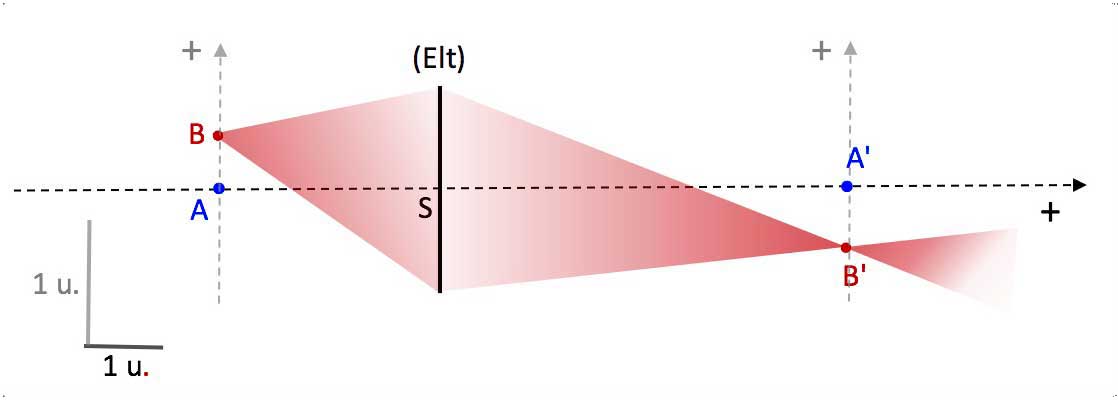
Fig. 9a.
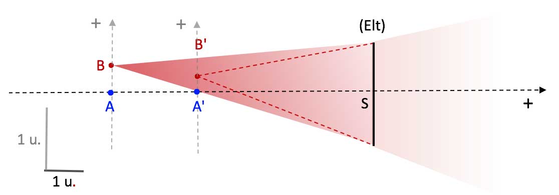
Fig. 9b.
Characterization of a thin simple optical element
*4 points ** * located on the optical axis that characterize optical behavoir : S , C, F' and F
-
S : vertex of the thin imager : indicates its position in space, and on the optical axis.
-
C : nodal point : by definition all rays (or its extension) that pass through nodal point C has unchanged direction when leaving the thin optical element. Position characterizes by its algebraic distance from vertex S : $\overline{SC}$.
The nodel point is a center (whose exact physical meaning depends of the type of thin simple optical element) -
F' : image focal point = second focal point = image focus : incident rays (or their extensions) parallel to the optical axis (or their extensions), after leaving the thin imager, pass through F'.
-
F : object focal point = first focal point = object focus : incident rays (or their extensions) passing through F leave (or their extensions) the imager parallel to the optical axis.
which define 3 important planes, perpendicular to the optical axis
- (Elt) : representation of the thin imager interface, contains S : incident rays (or their extension) change of direction when passing through (Elt).
- (P') : image focal plane = second focal plane , contains F' : all incident rays parallel to each other originated to a unic point at infinity leave (Elt) to converge (or their extension) on a unic image point B' located in (P'). Location of B' in (P') is the intersection of the ray passing through C with (P').
- (P) : object focal plane = first focal plane , contains F : all incident rays originated from a unic point source B leave (Elt) parallel to each other, given an image point B' located at infinity, in direction of the ray passing through C.
and 2 important algebraic distances
-
$f'=\overline{SF'}$ : algebraic distance from thin imager (Elt) to image focal plane (P) :
-
$f=\overline{SF}$ : algebraic distance from thin imager (Elt) to object focal plane (P).
Important significations of focal planes
Image focal plane :
-
Physical sense :
object B at infinity $\Longleftrightarrow |\overline{SB}| \ll |f|$. -
Object at infinity (P) $\Longleftrightarrow$ object in (P'), can be viewed by naked eye whether convergent or divergent optical element.
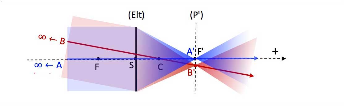
Fig. 10. Example : direct vision of the universe through a telescope (telescope is not a thin imager, but same image focal plane defintion).
- Object at infinity (P) $\Longleftrightarrow$ object in (P'), to be captured by an image sensor if convergent optical element.
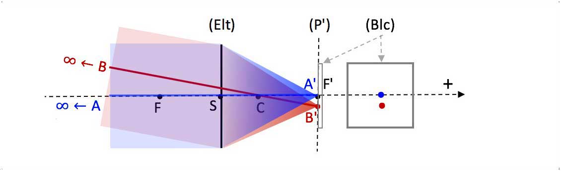
Fig. 11. Example : picture taken with a telephoto lens (telephoto lens is not a thin imager, but same image focal plane defintion).
Object focal plane (P)
-
Physical sense :
image B' at infinity $\Longleftrightarrow |\overline{SB'}| \ll |f'|$. -
Object in (P) $\Longleftrightarrow$ image at infinity
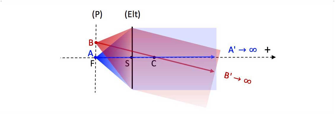
Fig. 12. Examples : the object can be the bulb of a lighthouse, or the film in a non-digital cinema projector (with quasi-parallel emerging beams in both cases, to illuminate front and far).
How to determine the image given by a thin simple optical element ?
Graphical study
Two different scales
-
Object and image : tranverse sizes $|\overline{AB}|$, $|\overline{A'B'};;\ll$ distances from optical element along optical axis $|\overline{SA}|$ , $|\overline{SA'}|$.
$\Longrightarrow$ dimensions perpendicular to optical axis $\ll$ dimensions along optical axis -
So Accurate graphical study $\Longrightarrow$ greatly magnify scale perpendicular to optical axis.
Fig. 13.
Determining of conjugate points
From given point (object or image) 3 specific light rays can be drawn ( only 2 required), whose intersection gives the conjugate point :
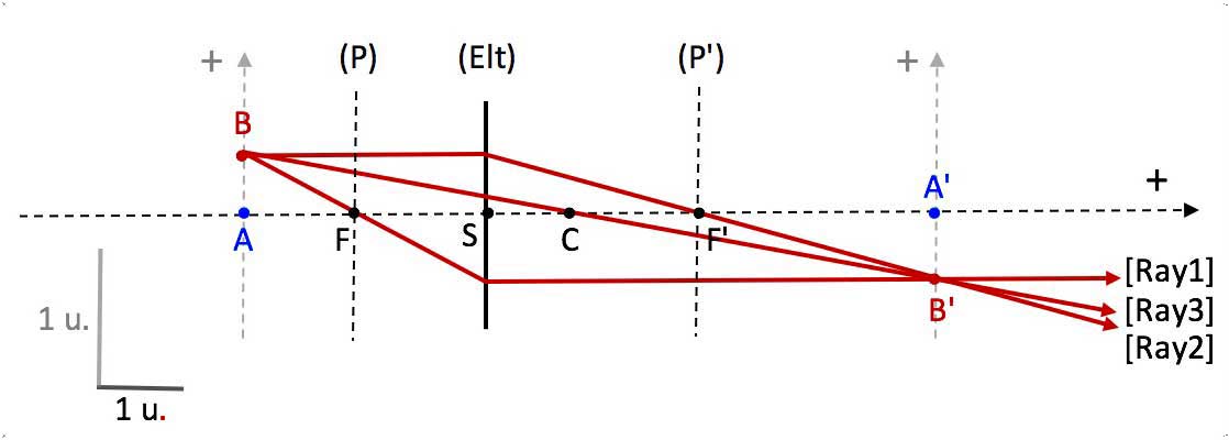
Fig. 14.
- [Ray1] : Incident rays (or their extensions) passing through the object focal point F leave (or their extensions) the imager parallel to the optical axis.
- [Ray2] : Incident rays (or their extensions) parallel to the optical axis pass (or their extensions), after leaving the thin imager, through the image focal point F'.
- [Ray3] : Incident ray (or its extension) passing through point C has unchanged direction when leaving the thin imager.
Consequences from focal points definitions
-
Incident rays parallel to each other intersect on a same point in the image focal plane (P').
(location : intersection of (P') with [Ray3]) -
Emergent rays parallel to each other diverge from a same point source located in the object focal plane (P).
(location : intersection of (P) with [Ray3])
Determining the emergent ray corresponding to any incident ray
-
deflection of a ray by a thin optical element : local interaction the point of impact (refraction or reflection) between incident ray and thin optical element $\Longrightarrow$ independent of the distance of the point source.
-
so consider point source B to infinity $\Longrightarrow$ image point B' would be in the image focal plane (P').
-
ray from B (to infinity) passing through point C has unchanged direction $\Longrightarrow$ location of B' in (P').
-
Emerging ray (or its extension) = straight line between impact point and B'.
Fig. 15.
Determining the incident ray corresponding to any emergent ray
-
deflection of a ray by a thin optical element : local interaction the point of impact (refraction or reflection) between emergent ray and thin optical element $\Longrightarrow$ independent of the distance of the image point.
-
so consider image point B' to infinity $\Longrightarrow$ point source B would be in the object focal plane (P).
-
emerging ray towards B (to infinity) passing through point C has unchanged direction $\Longrightarrow$ location of B in (P).
-
incident ray (or its extension) = straight line between impact point and B.
Analytical determining of conjugate points
Distance of the conjugate point from thin optical element
-
deduced from the thin optical element equation
-
thin optical element equation = thin optical element formula
-
will be given for :
- thin spherical mirror equation
- thin spherical refracting surface equation
- thin lens equation
(will be demonstrated in level foothills)
Distance of the conjugate point from optical axis
-
deduced from the transverse magnification $M_T$.
-
transverse magnification = lateral magnification
-
Definition : $M_T=\dfrac{\overline{A'B'}}{\overline{A'B'}}$
-
$M_T>0$ $\Longleftrightarrow$ erect image
$M_T<0$ $\Longleftrightarrow$ inverted image -
Expression : depends on type of simple optical element :
will be given for :
- thin spherical mirror equation
- thin spherical refracting surface equation
- thin lens equation -
algebraic value of $M_T$ : is a function of $\overline{AB}$ and $\overline{A'B'}$
$\Longrightarrow$ depends on conjugate points locations
$\Longrightarrow$ does not characterized the optical element itself.
How to characterize the action of an imager ?
Characterization of an extended object
-
Extended object [AB] or [B$_1$B$_2$], perpendicularly to the optical axis :
- characterized by the algebraic transverse size (distance between its extremities) : $\overline{AB}$ or $\overline{B_1B_2}$
- or characterized by the apparent angle (in algebraic value or not) substended by the object at nodal point of the eye (direct vision) or nodal point of the thin imager : $\alpha$ or $\overline{\alpha}$ -
Extended object [A$_1$A$_2$] along the optical axis :
characterized by the algebraic longitudinal size (distance between its extremities) : $\overline{A_1A_2}$
Characterization of its conjugate extended image
-
Extended image [A'B'] or [B'$_1$B'$_2$], perpendicularly to the optical axis :
- characterized by its algebraic size (distance between its extremities) : $\overline{A'B'}$ or $\overline{B_1'B_2'}$
- or characterized by the apparent angle (in algebraic value or not) substended by the object at nodal point of the eye (direct vision) or nodal point of the thin imager : $\alpha$ or $\overline{\alpha}$ -
Extended image [A'$_1$A'$_2$] along the optical axis :
characterized by the algebraic size (distance between its extremities) : $\overline{A'_1A'_2}$
Characterization of the imager action on an extended object
The imager gives an image of an object. The characterization of imager action depends on how the object and the image are characterized.
Transverse magnification of the extended object
- Object and image both characterized by their algebraic transverse sizes :
$\Longrightarrow$ imager action characterized by the transverse magnification $M_T$
$M_T=\dfrac{image:size}{object:size}=\dfrac{\overline{A'B'}}{\overline{AB}}$
Apparent magnification of the extended object
- Object and image both characterized their apparent angles :
$\Longrightarrow$ imager action characterized by the apparent magnification $M_A$
apparent magnification = angular magnification
$M_A=\dfrac{image:apparent:angle}{object:apparent:angle}=\dfrac{\overline{ \alpha '}}{\overline{ \alpha }}$
or $M_A=\pm\dfrac{ \alpha '}{ \alpha }$, with sign + when erect image, sign - when inverted image.
Fig. 16. In this experiment, the observed object is located at a certain distance from the magnifying glass, as well as the eye of the observer. For these conditions of use, the magnifying glass gives a magnification of +2.5. There are optimum conditions for using the magnifying glass (see chapter "optical instruments").
!!!! BE CAREFUL
!!!!An apparent angle depends on distance from the object or the image to the nodal point of the observing system (human eye or telephoto lens of a camera for example) $\Longrightarrow$ more accurate definitions of apparent angles will be necessary (see chapter "optical instruments").
Longitudinal magnification of the extended object
- Object and image both characterized by their algebraic longitudinal sizes :
$\Longrightarrow$ imager action characterized by the longitudinal magnification $M_L$
$M_L=\dfrac{image:size}{object:size}=\dfrac{\overline{A'_1A_2'}}{\overline{A_1A_2}}$