9.9 KiB
| title | media_order |
|---|---|
| Spherical refracting surface : overview | dioptre-1.gif |
What is a refracting interface ?
Refracting surface : physical description
-
Interface separating two transparent media of different refractive indices.
-
can be found in nature :
Examples :
- a plane refracting surface : the flat and quiet surface of a lake. - a spherical refracting surface : a fish ball aquarium.

Fig. 1. The spherical refracting interface of a fish ball aquarium.
- appears in the design and modeling of other optical elements :
Examples :
- a glass window pane is the combinaison of two parallel plane refracting interfaces (air/glass, then glass/air), separated by the thickness of the pane.
- a lens is composed of two consecutive curved (often spherical) refracting interfaces (air/glass, then glass/air) that are rotational symmetrical around a same axis.
Refracting interface versus refracting surface
!!!! DIFFICULT POINT : One plane or spherical refracting interface has two different optical behaviors for image formation,
is characterized by two different sets of parameters, depending of the direction of the light propagation.
!!!!
!!!!Consider a plane interface (a thick window whose thickness and effect can be neglected) separating air and water,
and two twins (Thompson and Thomson) at equal distances on both sides of the interfaces (Fig. 2a).
!!!!
!!!! 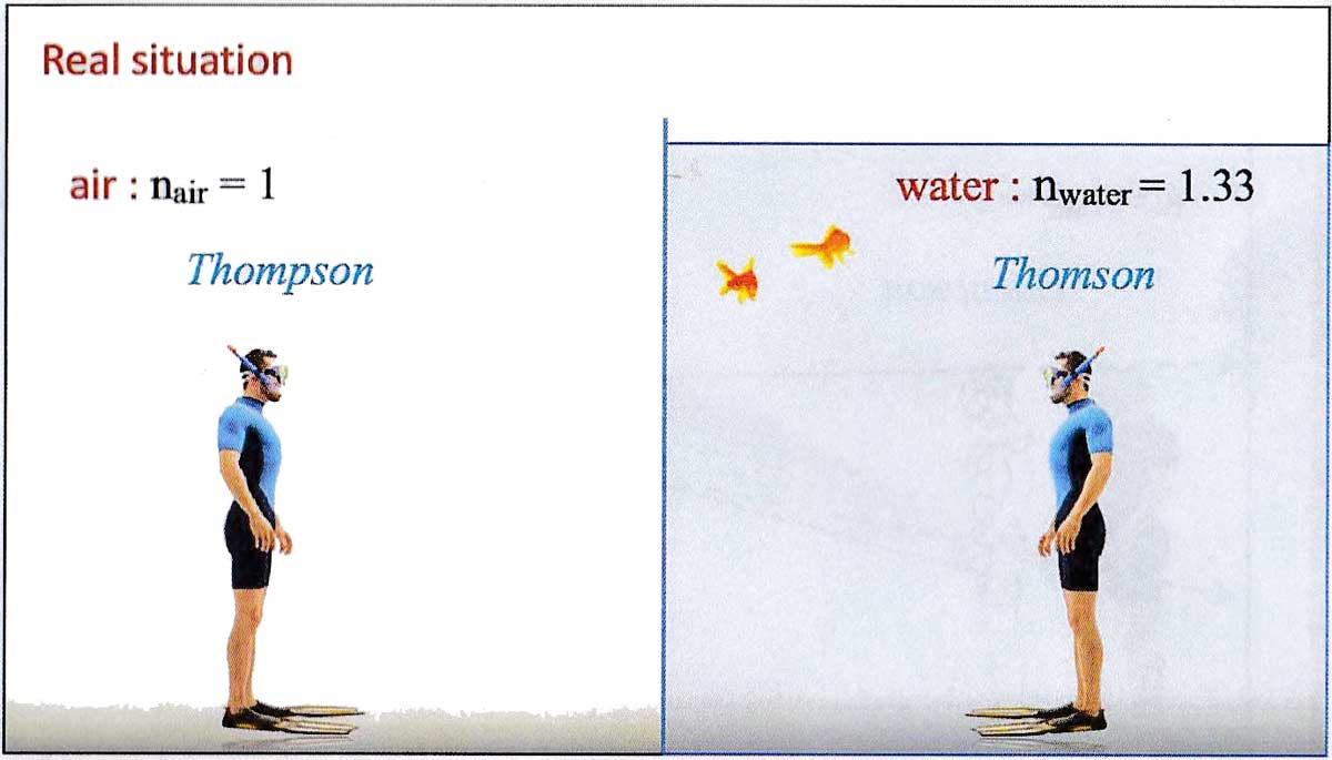
!!!! Fig. 2a : The situation is not symmetrical.
!!!!
!!!! * When Thompson (in air) looks at Thomson (in water), the light propagates from Thomson to Thompson’s eyes.
The fact is that Thompson sees the image of his brother closer than the real position of his brother (Fig. 2b)
!!!!
!!!! 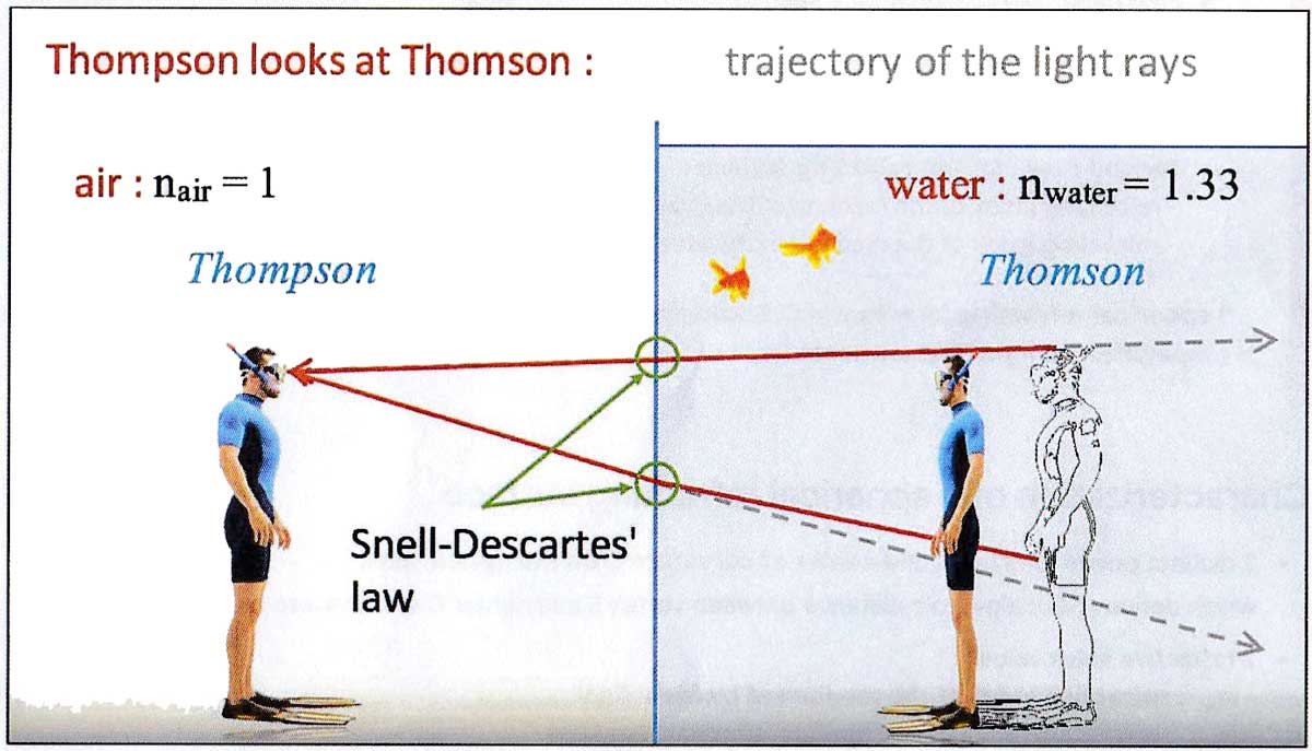
!!!! Fig. 2b. Thompson sees his brother closer than his real position in water.
!!!!
!!!! * In the opposite situation, when Thomson (in water) looks at Thompson (in air),
the light propagates from Thompson to Thomson’s eyes.
And the fact is that Thomson sees the image of his brother farther away than his real position (Fig. 2c)
!!!! (Strictly speaking, the eye of a fish should be considered in this situation, eyes well adapted to the vision in water,
and in direct contact with water. If not, we should consider that the Thompson’s dive mask is filled with water,
to have Thomson’s eyes in contact with water and not add another water/air refracting interface
(that of the dive mask) on the path of the light).
!!!!
!!!! 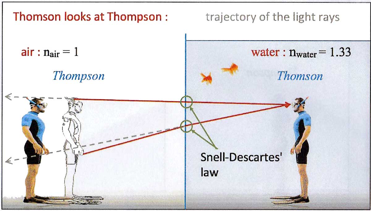
!!!! Fig. 2c. Thomson sees in brother farther than his real position in air.
!!!!
!!!! All this can be predicted and calculated, but this example shows that this air/water plane
refracting interface corresponds to two different plane refracting surfaces :
!!!!
!!!! * First case , refracting surface such as :
!!!! - refracting index of the medium of the incident light : $n_{inc} = n_{water} = 1.33$
!!!! - refracting index of the medium of the emergent light : $n_{eme} = n_{air} = 1$
!!!!
!!!! *¨ Second case , refracting surface such as :
!!!! - refracting index of the medium of the incident light : $n_{inc} = n_{air} = 1$
!!!! - refracting index of the medium of the emergent light : $n_{eme} = n_{water} = 1.33$.
!!!!
Difference in terminology between Spanish, French and English
!!!! BE CAREFUL :
!!!! In the same way as we use in English the single word "mirror" to qualify a "reflecting surface", in French is use the single word "dioptre" to qualify a "refracting surface".
!!!! The term "dioptre" in English is a unit of mesure of the vergence of an optical system. In French, the same unit of measure is named "dioptrie".
!!!! So keep in mind the following scheme :
!!!!
!!!! refracting surface : EN : refracting surface , ES : superficie refractiva , FR : dioptre.
!!!! A crystal ball forms a spherical refracting surface : un "dioptre sphérique" in French.
!!!!
!!!! unit of measure : EN : dioptre , ES : dioptría , FR : dioptrie.
!!!! My corrective lens for both eyes are 4 dioptres : "4 dioptries" in French.
Non stigmatism of spherical refracting surfaces
Ray tracing study of a spherical refracting surface :
Click here for geogebra animation
- At each impact point of the rays upon the spherical refracting surface, the Snell-Descartes relation applies.

- A spherical refracting surface is not stigmatic : The rays (or their extensions) originating from a same object point and that emerge from the surfac egenerally do not converge towards an image point.

- If we limit the opening of the spherical refracting surface so that only the rays meeting the surface near the vertex are refracted through the surface.

- and if the object points remain close enough to the optical axis, so that the angles of incidence and refraction remain small, then for each object point an image point can be almost defined, and therefore the spherical refracting surface becomes quasi-stigmatic.

Gauss conditions / paraxial approximation and quasi-stigmatism
When spherical refracting surfaces are used under the following conditions, named Gauss conditions :
- All incident rays lie close to the optical axis
- The angles of incidence and refraction are small
Then the spherical refracting surfaces can be considered quasi-stigmatic, and therefore they can be used to build optical images.
Mathematically, when an angle $\alpha$ is small $\alpha < or \approx 10 ^\circ$, the following approximations can be made :
$sin(\alpha) \approx tan (\alpha) \approx \alpha$, and $cos(\alpha) \approx 1$.
Geometrical optics limited to Gaussian conditions is called Gaussian optics or paraxial optics.
Thin spherical refracting surface
We call thin spherical refracting surface a spherical refracting surface used in the Gauss conditions.
How is modeled a spherical refracting surface in paraxial optics ?
Characterization of a spherical refracting surface
-
2 distincts points : vextex S and center of curvature C on the optical axis, which defines $
\overline{SC}$ : algebraic distance between vertex S and center C of curvature on optical axis. -
2 refractive index values :
- $n_{inc}$ : refractive index of the medium of the incident light.
- $n_{eme}$ : refractive index of the medium of the emergent light. -
1 arrow : indicates the direction of light propagation

Analytical study
-
Thin spherical refracting surface equation = conjuction equation for a spherical refracting surface
$\dfrac{n_{eme}}{\overline{SA_{ima}}}-\dfrac{n_{inc}}{\overline{SA_{obj}}}=\dfrac{n_{eme}-n_{inc}}{\overline{SC}}$ (equ.1) -
Transverse magnification expression
$\overline{M_T}=\dfrac{n_{inc}\cdot\overline{SA_{ima}}}{n_{eme}\cdot\overline{SA_{obj}}}$ (equ.2)
You know $\overline{SA_{obj}}$, $n_{inc}$ and $n_{eme}$, you have previously calculated $\overline{SA_{ima}}$, so you can calculate $\overline{M_T}$ and deduced $\overline{A_{ima}B_{ima}}$.
! USEFUL : The conjuction equation and the transverse magnification equation for a plane refracting
!surface are obtained by rewriting these equations for a spherical refracting surface in the limit when
!
! $|\overline{SC}|\longrightarrow\infty$.
! Then we get for a plane refracting surface :
!
! * conjuction equation : $\dfrac{n_{fin}}{\overline{SA_{ima}}}-\dfrac{n_{ini}}{\overline{SA_{obj}}}=0$ (equ.3)
!
! * transverse magnification equation : $\dfrac{n_{ini}\cdot\overline{SA_{ima}}}{n_{fin}\cdot\overline{SA_{obj}}}$
(equ.2, unchanged)
! but (equ.3) gives $\dfrac{\overline{SA_{ima}}}{\overline{SA_{obj}}}=\dfrac{n_{inc}}{n_{eme}}$.
! Copy this result into (equ.2) leads to $\overline{M_T}=+1$.
Graphical study
1 - Determining object and image focal points
Positions of object focal point F and image focal point F’ are easily obtained from the conjunction equation (equ. 1).
-
Image focal length $
\overline{OF'}$ : $\left(|\overline{OA_{obj}}|\rightarrow\infty\Rightarrow A_{ima}=F'\right)$
(equ.1)$\Longrightarrow\dfrac{n_{eme}}{\overline{SF'}}=\dfrac{n_{eme}-n_{inc}}{\overline{SC}}$$\Longrightarrow\overline{SF'}=\dfrac{n_{eme}\cdot\overline{SC}}{n_{eme}-n_{inc}}$ -
Object focal length $
\overline{OF}$ : $\left(|\overline{OA_{ima}}|\rightarrow\infty\Rightarrow A_{obj}=F\right)$
(equ.1) $\Longrightarrow-\dfrac{n_{inc}}{\overline{SF}}=\dfrac{n_{eme}-n_{inc}}{\overline{SC}}$$\Longrightarrow\overline{SF}=-\dfrac{n_{inc}\cdot\overline{SC}}{n_{eme}-n_{inc}}$
2 - Thin spherical refracting surface representation
-
Optical axis = revolution axis of the refracting surface, positively oriented in the direction of propagation of the light (from the object towards the refracting surface)
-
Thin spherical refracting surface representation :
- line segment, perpendicular to the optical axis, centered on the axis with symbolic indication of the direction of curvature of the surface at its extremities.
- vertex S, that locates the refracting surface on the optical axis.
- nodal point C = center of curvature.
- object focal point F and image focal point F’.
Non stigmatism of spherical refracting surfaces
Ray tracing study of a spherical refracting surface :
Click here for geogebra animation