12 KiB
| title | media_order |
|---|---|
| Le dioptre sphérique, en approximation paraxiale : synthèse | dioptre1ok.png,dioptre2ok.png,dioptre3ok.png,dioptre4ok.png |
Qu'est-ce qu'une interface réfractante ?
Interface réfractante : description physique
-
Interface séparant deux milieux transparents d'indices de réfraction différents..
-
peut être trouvée dans la nature :
Exemples :
- une interface réfractante plane : la surface plane d'un lac tranquille. - une interface réfractante sphérique : un aquarium boule.

Fig. 1. L'interface réfranctante sphérique d'un aquarium boule.
- **apparaît dans la conception et modélisation de composants optiques ** :
Exemples :
- une vitre en verre se décompose en deux interface réfractantes planes (air/verre, puis verre/air), séparées par l'épaisseur de la vitre.
- une lentille est la succession de deux interfaces réfractantes courbes (souvent sphériques) consécutives (air/verre, puis verre/air) qui présentent toutes deux une symétrie de révolution autour d'un même axe.
Interface réfractante versus surface réfractante
!!!! POINT DIFFICILE : une interface réfractante plane ou sphérique présente deux comportements optiques différents pour la formation d'image,
est caractérisée par deux ensembles de paramètres de veleurs différentes, selon que la lumière considérée traverse l'interface dans un sens ou dans l'autre.
!!!!
!!!!Considère une interface plane (une vitre épaisse dont l'épaisseur et donc l'effet optique peuvent être négligés) séparant de l'air et de l'eau,
et deux jumeaux (Thompson and Thomson) à égales distances de chaque côté de l'interface (Fig. 2a).
!!!!
!!!! 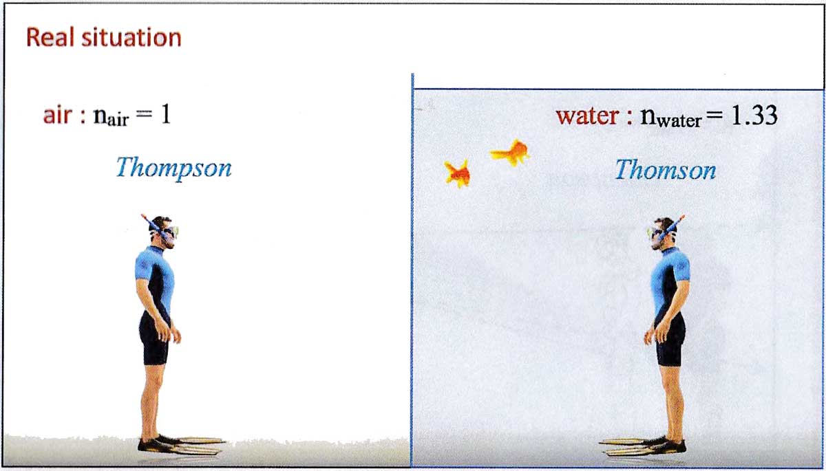
!!!! Fig. 2a : La situation n'est pas symétrique.
!!!!
!!!! * Quand Thompson (dans l'ir) regarde Thomson (dans l'eau), la lumière se propage de Thomson vers les yeux de Thompson.
!!!! Le fait est que Thompson voit l'image de son frère plus proche que la position réelle de ce son frère (Fig. 2b)
!!!!
!!!! 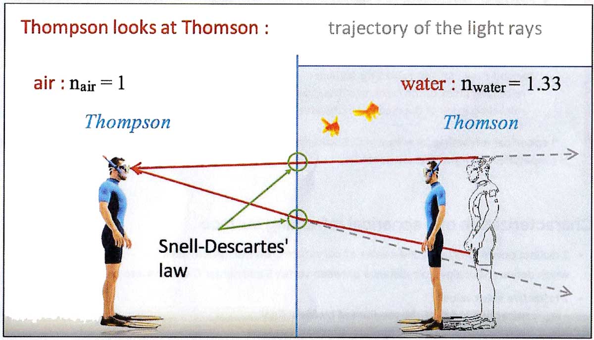
!!!! Fig. 2b. Thompson voit son frère plus proche que sa position réelle dans l'eau.
!!!!
!!!! * Dans la situation opposée, quand Thomson (dans l'eau) regarde Thompson (dans l'air),
la lumière se propage de Thompson jusqu'aux yeux de Thomson.
Et le fait est que Thomson voit l'image de son frère plus loin que sa position réelle (Fig. 2c)
!!!! (en toute rigueur, les yeux d'un poisson devraient être considérés dans cet exemple, des yeux plus adaptés
à la vision sous-marine et des yeux en contact direct avec l'eau. Sinon, nous devrions considérer que le masque de plongée
de Thompson est rempli d'eau pour ne pas ajouter déjà une autre interface eau/air (celle du masque de plongé) sur
la trajectoire de la lumière).
!!!!
!!!! 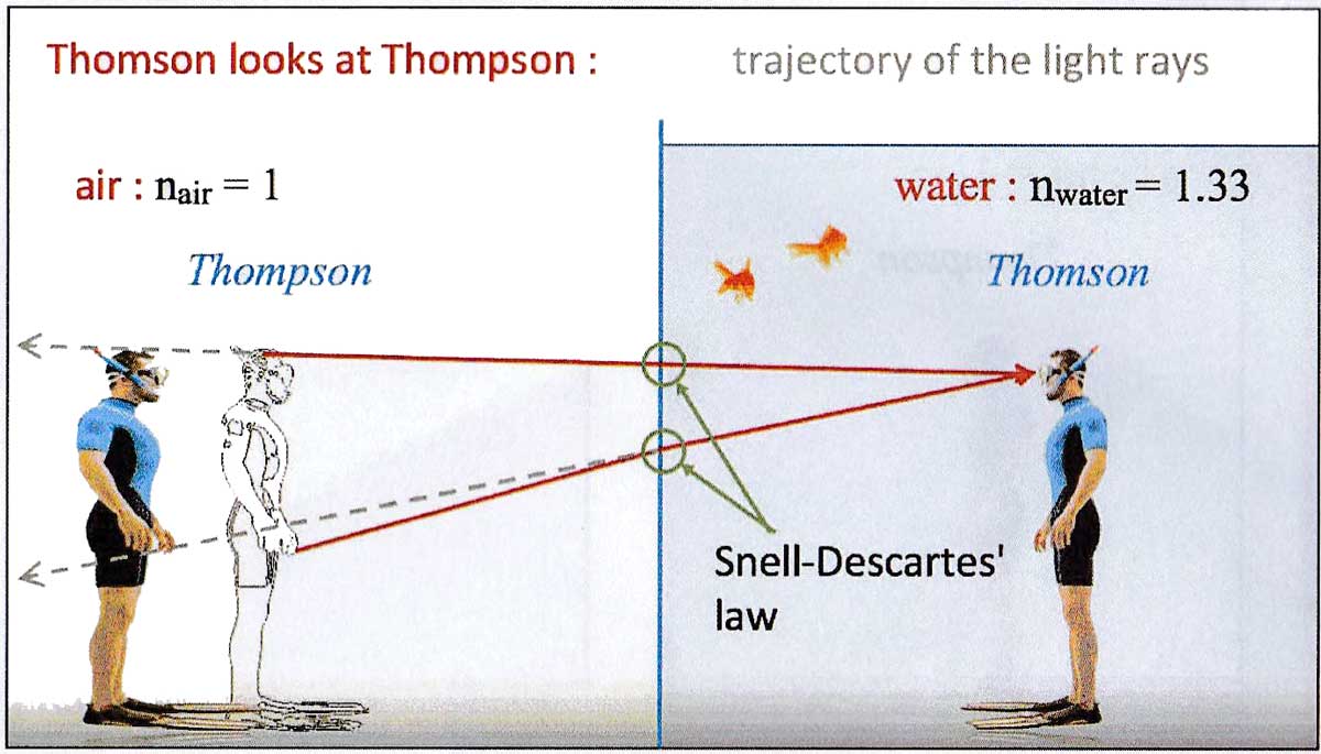
!!!! Fig. 2c. Thomson voit son frère plus loin que sa position réelle dans l'air.
!!!!
!!!! Tout ceci peut être calculé et prédit, mais cet exemple montre que cette interface réfratante plane air/eau
correspond à deux surface réfrantantes:
!!!!
!!!! * Premier cas, la surface réfractante est telle que :
!!!! - indice de réfraction de milieu de la lumière incidente : $n_{inc} = n_{water} = 1.33$
!!!! - indice de réfraction de milieu de la lumière émergente : $n_{eme} = n_{air} = 1$
!!!!
!!!! *¨ Deuxième cas, la surface réfractante est telle que :
!!!! - indice de réfraction de milieu de la lumière incidente : $n_{inc} = n_{air} = 1$
!!!! - indice de réfraction de milieu de la lumière émergente : $n_{eme} = n_{water} = 1.33$.
!!!!
Un dioptre est une surface réfractante dont un sens de propagation de la lumière est précisé.
Différence de terminologie entre l'espagnol, le français et l'anglais.
!!!! ATTENTION :
!!!! In the same way as we use in English the single word "mirror" to qualify a "reflecting surface", in French is use the single word "dioptre" to qualify a "refracting surface".
!!!! The term "dioptre" in English is a unit of mesure of the vergence of an optical system. In French, the same unit of measure is named "dioptrie".
!!!! So keep in mind the following scheme :
!!!!
!!!! refracting surface : EN : refracting surface , ES : superficie refractiva , FR : dioptre.
!!!! A crystal ball forms a spherical refracting surface : un "dioptre sphérique" in French.
!!!!
!!!! unit of measure : EN : dioptre , ES : dioptría , FR : dioptrie.
!!!! My corrective lens for both eyes are 4 dioptres : "4 dioptries" in French.
Non stigmatism of spherical refracting surfaces
Ray tracing study of a spherical refracting surface :
Click here for geogebra animation
- At each impact point of the rays upon the spherical refracting surface, the Snell-Descartes relation applies.

- A spherical refracting surface is not stigmatic : The rays (or their extensions) originating from a same object point and that emerge from the surfac egenerally do not converge towards an image point.

- If we limit the aperture of the spherical refracting surface so that only the rays meeting the surface near the vertex are refracted through the surface.

- and if the object points remain close enough to the optical axis, so that the angles of incidence and refraction remain small, then for each object point an image point can be almost defined, and therefore the spherical refracting surface becomes quasi-stigmatic.

Gauss conditions / paraxial approximation and quasi-stigmatism
When spherical refracting surfaces are used under the following conditions, named Gauss conditions :
- All incident rays lie close to the optical axis
- The angles of incidence and refraction are small
Then the spherical refracting surfaces can be considered quasi-stigmatic, and therefore they can be used to build optical images.
Mathematically, when an angle $\alpha$ is small $\alpha < or \approx 10 ^\circ$, the following approximations can be made :
$sin(\alpha) \approx tan (\alpha) \approx \alpha$, and $cos(\alpha) \approx 1$.
Geometrical optics limited to Gaussian conditions is called Gaussian optics or paraxial optics.
Thin spherical refracting surface
We call thin spherical refracting surface a spherical refracting surface used in the Gauss conditions.
How is modeled a spherical refracting surface in paraxial optics ?
Characterization of a spherical refracting surface
-
2 distincts points : vextex S and center of curvature C on the optical axis, which defines $
\overline{SC}$ : algebraic distance between vertex S and center C of curvature on optical axis. -
2 refractive index values :
- $n_{inc}$ : refractive index of the medium of the incident light.
- $n_{eme}$ : refractive index of the medium of the emergent light. -
1 arrow : indicates the direction of light propagation

Analytical study
-
Thin spherical refracting surface equation = conjuction equation for a spherical refracting surface
$\dfrac{n_{eme}}{\overline{SA_{ima}}}-\dfrac{n_{inc}}{\overline{SA_{obj}}}=\dfrac{n_{eme}-n_{inc}}{\overline{SC}}$ (equ.1) -
Transverse magnification expression
$\overline{M_T}=\dfrac{n_{inc}\cdot\overline{SA_{ima}}}{n_{eme}\cdot\overline{SA_{obj}}}$ (equ.2)
You know $\overline{SA_{obj}}$, $n_{inc}$ and $n_{eme}$, you have previously calculated $\overline{SA_{ima}}$, so you can calculate $\overline{M_T}$ and deduced $\overline{A_{ima}B_{ima}}$.
! USEFUL : The conjuction equation and the transverse magnification equation for a plane refracting
!surface are obtained by rewriting these equations for a spherical refracting surface in the limit when
!
! $|\overline{SC}|\longrightarrow\infty$.
! Then we get for a plane refracting surface :
!
! * conjuction equation : $\dfrac{n_{fin}}{\overline{SA_{ima}}}-\dfrac{n_{ini}}{\overline{SA_{obj}}}=0$ (equ.3)
!
! * transverse magnification equation : $\dfrac{n_{ini}\cdot\overline{SA_{ima}}}{n_{fin}\cdot\overline{SA_{obj}}}$
(equ.2, unchanged)
! but (equ.3) gives $\dfrac{\overline{SA_{ima}}}{\overline{SA_{obj}}}=\dfrac{n_{inc}}{n_{eme}}$.
! Copy this result into (equ.2) leads to $\overline{M_T}=+1$.
Graphical study
1 - Determining object and image focal points
Positions of object focal point F and image focal point F’ are easily obtained from the conjunction equation (equ. 1).
-
Image focal length $
\overline{OF'}$ : $\left(|\overline{OA_{obj}}|\rightarrow\infty\Rightarrow A_{ima}=F'\right)$
(equ.1)$\Longrightarrow\dfrac{n_{eme}}{\overline{SF'}}=\dfrac{n_{eme}-n_{inc}}{\overline{SC}}$ $\Longrightarrow\overline{SF'}=\dfrac{n_{eme}\cdot\overline{SC}}{n_{eme}-n_{inc}}$ (equ.4) -
Object focal length $
\overline{OF}$ : $\left(|\overline{OA_{ima}}|\rightarrow\infty\Rightarrow A_{obj}=F\right)$
(equ.1) $\Longrightarrow-\dfrac{n_{inc}}{\overline{SF}}=\dfrac{n_{eme}-n_{inc}}{\overline{SC}}$ $\Longrightarrow\overline{SF}=-\dfrac{n_{inc}\cdot\overline{SC}}{n_{eme}-n_{inc}}$ (equ.5)
!!!! ADVISE :
!!!! Memory does not replace understanding. Do not memorise (equ.4) and (equ.5), but understand
!!!! the definitions of the object and image focal points, and know how to find these two equations
!!! from the conjuction equation for a spherical refracting surface.
!!!!
! NOTE 1 :
! An optical element being convergent when the image focal point is real,
! so when $\overline{OF}>0$ (with optically axis positively oriented in the direction of the light propagation),
! you can deduce from (equ.4) that is spherical refracting surface is convergent if and only if its center
! of curvature C is in the mmedium of highest refractive index.
!
2 - Thin spherical refracting surface representation
-
Optical axis = revolution axis of the refracting surface, positively oriented in the direction of propagation of the light (from the object towards the refracting surface)
-
Thin spherical refracting surface representation :
- line segment, perpendicular to the optical axis, centered on the axis with symbolic indication of the direction of curvature of the surface at its extremities.
- vertex S, that locates the refracting surface on the optical axis.
- nodal point C = center of curvature.
- object focal point F and image focal point F’.
! NOTE 2
! The direction of the curvature does not presume the convergent or divergent character
! of the diopter. It also depends on the refractive index values on each side of the spherical
! refracting surface. look at what happens to the incident ray parallel to the optical axis
in Figures 3 and 4, and 5 and 6 below, and review NOTE 1.
!
Examples of graphical situations, with analytical results to train
!!!! IMPORTANT :
!!!! Even for only one of the following figures, the real or virtual character of the
!!!! image may depend on the position of the object. This paragraph is only for you
!!!! to understand how to determine the 3 rays that determine the image. It is
!!!! important not to memorize these figures, which would be limiting, misleading
!!!! and without interest.
!!!!
!!!! All the useful numerical values are given for each figure, making it possible
!!!! also to check that you master the analytical study of each presented case.
!!!!
Click here for geogebra animation
- with real objects
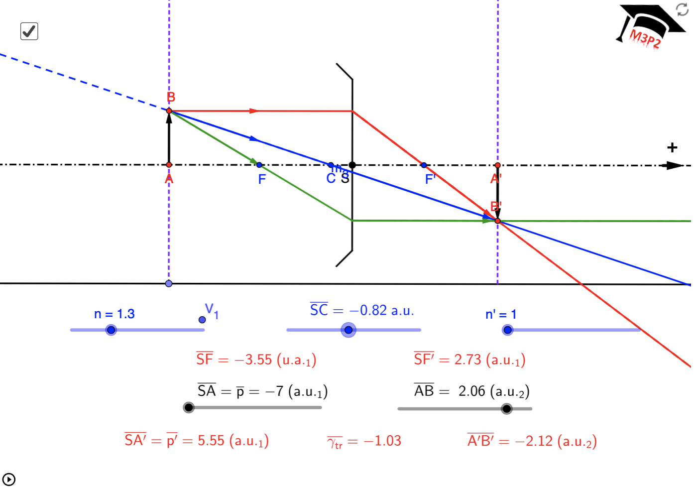
Fig. 4.
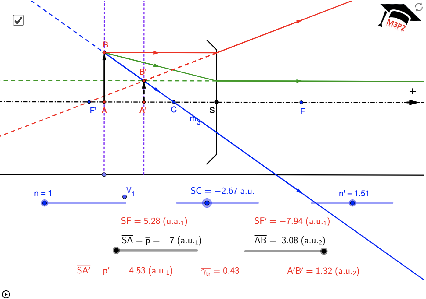
Fig. 5.
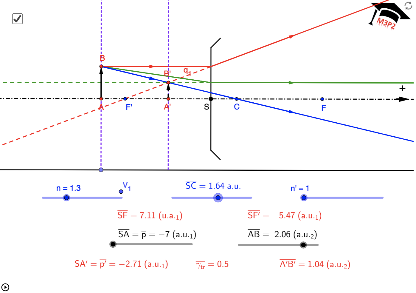
Fig. 6.
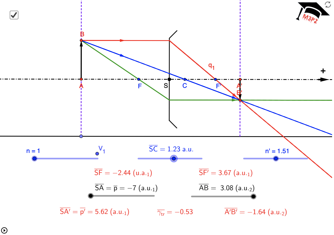
Fig. 7.
- with virtual objects
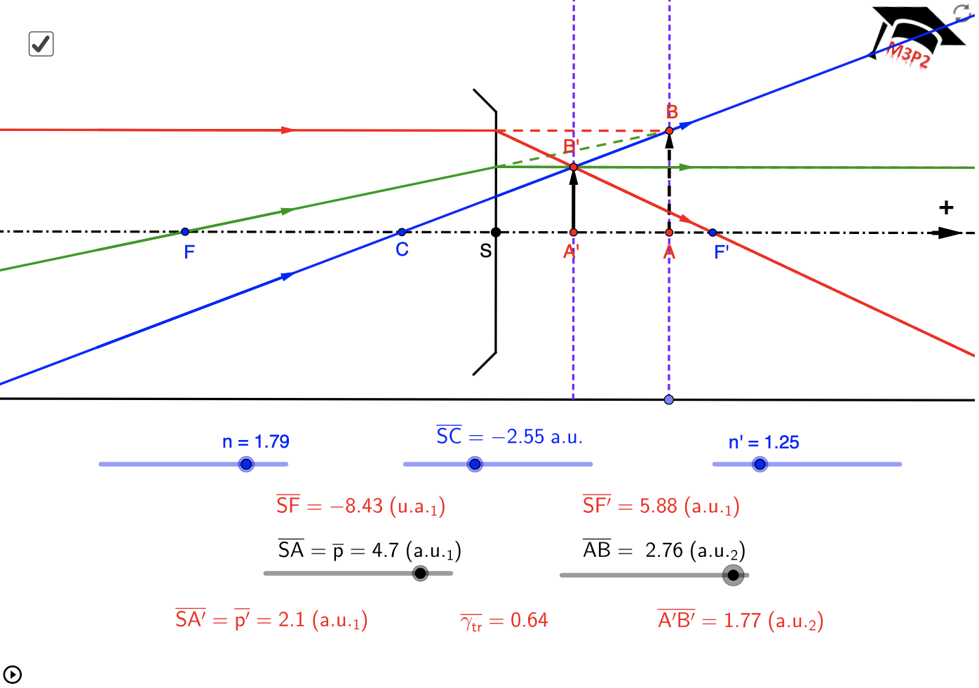
Fig. 8.
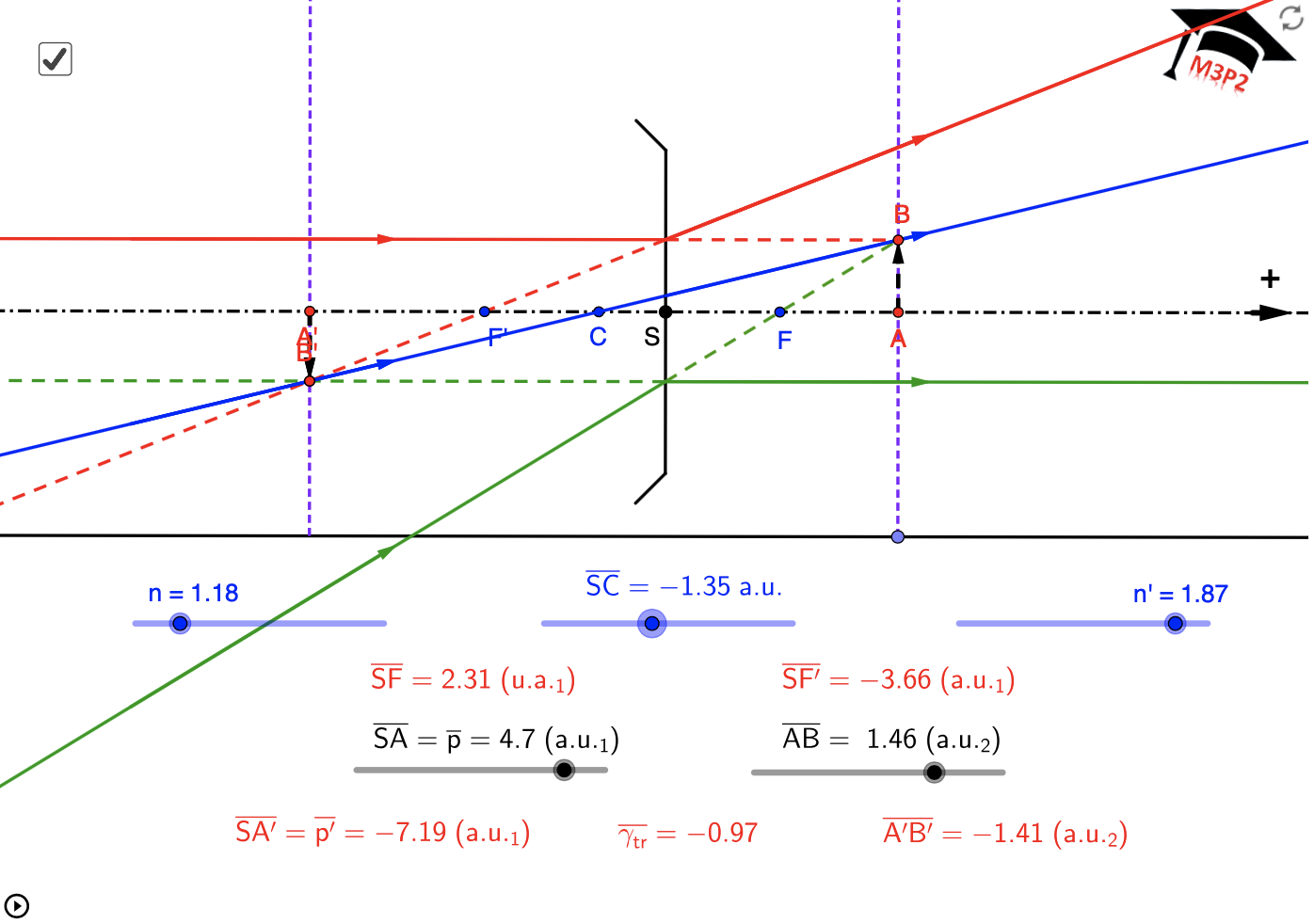
Fig. 9.
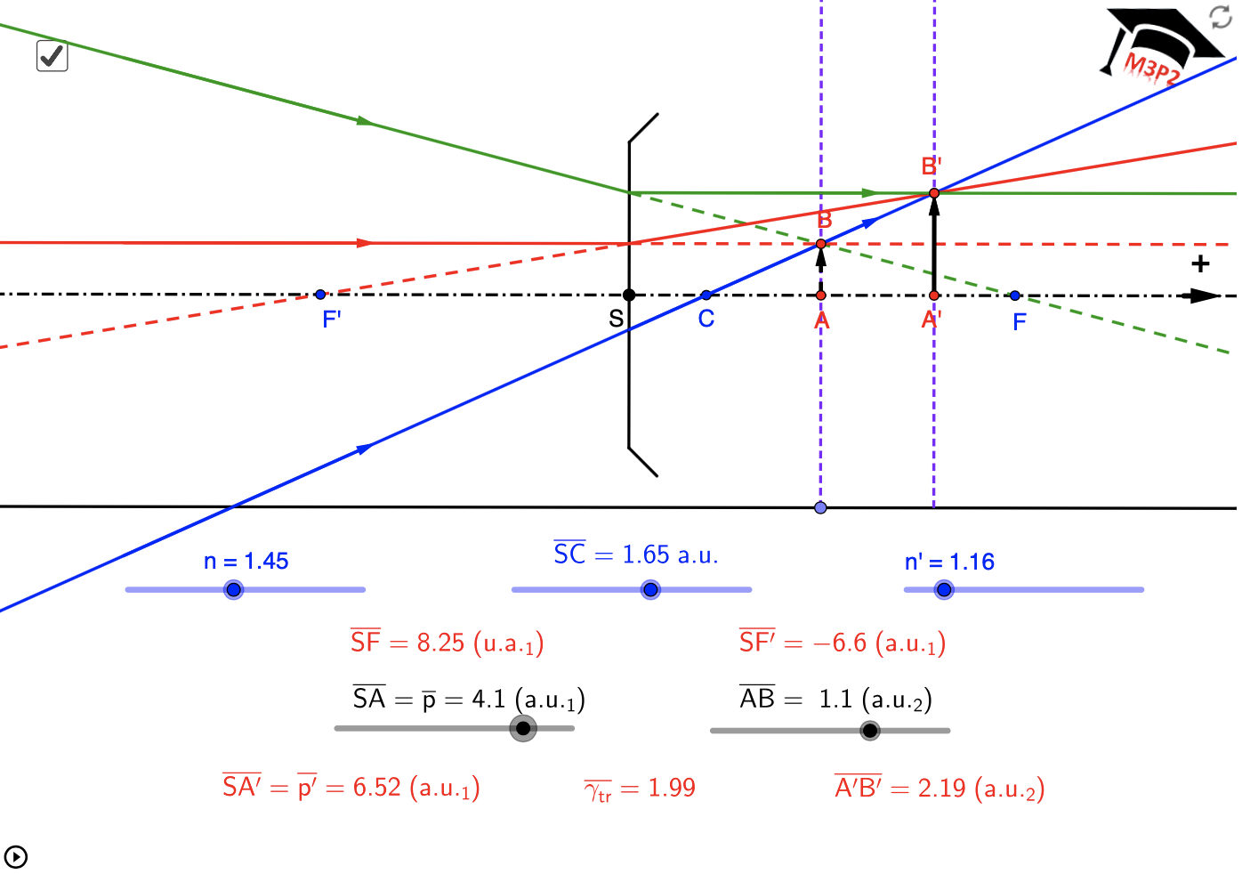
Fig. 10.
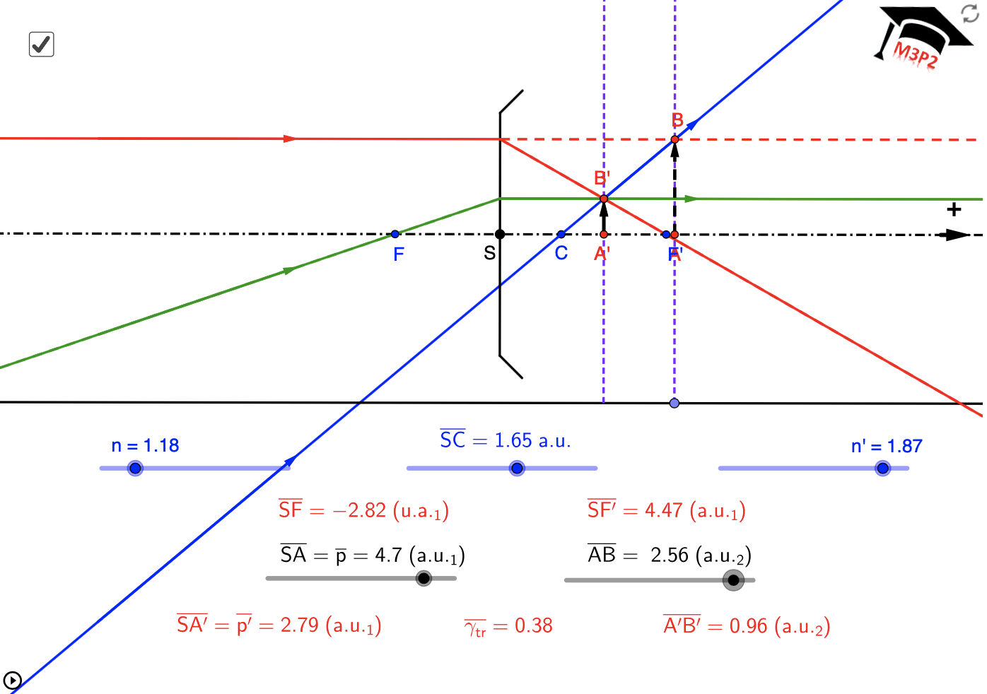
Fig. 11.